ラズパイPicoW(Raspberry Pi Pico W)に液晶ディスプレイ(LCD)を接続し、I2C通信を使って文字を表示させます。
実験準備
実験に必要な機器と部品を準備します。
機器
「ラズパイPicoWを始めよう。」記事で書きましたラズパイPicoWと、統合開発環境ThonnyとMicroPythonファームウェアをインストールしたRaspi4Bを準備します。
部品
液晶ディスプレイ(LCD)、I2CシリアルI/Fモジュールなど実験に使う部品を準備します。
| 部 品 名 | 規 格 | 数 量 | 取扱い店(参考) |
| 液晶ディスプレイ(LCD) | LCD 1602A | 1 | Amazon (セット) |
| I2CシリアルI/Fモジュール | LCM1602 | ||
| ブレッドボード | BB-102 | 1 | 秋月電子通商 |
| ジャンパーワイヤ | メス-メス (約20cm) | 1 | 電子工作ステーション |
機器と部品の配線
準備した機器と部品を実際につなぎ、MicroPythonでプログラミングを行い、液晶ディスプレイ(LCD)に文字を表示させます。
配線リスト
ブレッドボードを使って、液晶ディスプレイ(LCD)などをジャンパーワイヤでつなぎます。
GPI6とGP17にI2Cピンを接続しますが、プログラムコードを調整すれば、他のI2Cピンを使うこともできます。
液晶ディスプレイ(LCD)のVCCピンは5Vに接続する必要があります。
| ラズパイPicoW | 液晶ディスプレイ(LCD) | 備 考 |
| GP16 | SDA | |
| GP17 | SCL | |
| VBUS (5V) | VCC | |
| GND | GND |
配線図
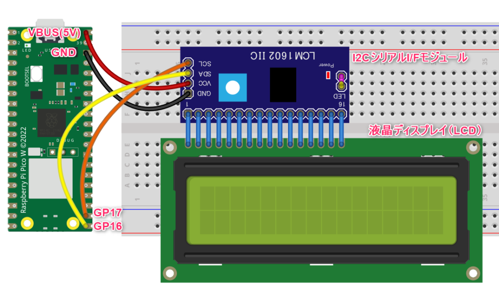
液晶ディスプレイ(LCD)とI2CシリアルI/Fモジュールは、ブレッドボード内部の配線で接続します。
外部ライブラリの保存
LCDと通信をするために、Tyler Peppy氏(GitHubユーザー)が開発したライブラリ、「 lcd_api.py」と「 pico_i2c_lcd.py」の2種類のモジュールを組み合わせて使います。
このライブラリは、MIT Licenseのもとで配布されています。
MIT License

Copyright (c) 2023 Tyler Peppy

Permission is hereby granted, free of charge, to any person obtaining a copy of this software and associated documentation files (the "Software"), to deal in the Software without restriction, including without limitation the rights to use, copy, modify, merge, publish, distribute, sublicense, and/or sell copies of the Software, and to permit persons to whom the Software is furnished to do so, subject to the following conditions:

The above copyright notice and this permission notice shall be included in all copies or substantial portions of the Software.

THE SOFTWARE IS PROVIDED "AS IS", WITHOUT WARRANTY OF ANY KIND, EXPRESS OR IMPLIED, INCLUDING BUT NOT LIMITED TO THE WARRANTIES OF MERCHANTABILITY, FITNESS FOR A PARTICULAR PURPOSE AND NONINFRINGEMENT. IN NO EVENT SHALL THE AUTHORS OR COPYRIGHT HOLDERS BE LIABLE FOR ANY CLAIM, DAMAGES OR OTHER LIABILITY, WHETHER IN AN ACTION OF CONTRACT, TORT OR OTHERWISE, ARISING FROM, OUT OF OR IN CONNECTION WITH THE SOFTWARE OR THE USE OR OTHER DEALINGS IN THE SOFTWARE.
外部モジュールは、GitHubから直接ダウンロードして入手するか、コマンドを使ってインストールする方法が一般的ですが、今回は入手したコードをThonnyのエディタに貼りつけて、指定のフォルダ(ディレクトリ)に保存します。
libフォルダ(ディレクトリ)の作成
MicroPythonは外部モジュールをインポートする際、ラズパイPicoWの「lib」フォルダ(ディレクトリ)を参照します。
「lib」フォルダ(ディレクトリ)が存在しない場合は、次の手順で新たに作成します。
Raspi4BのThonnyを起動後、メニューの「表示」をクリックして、ダイアログから「ファイル」を選択します。
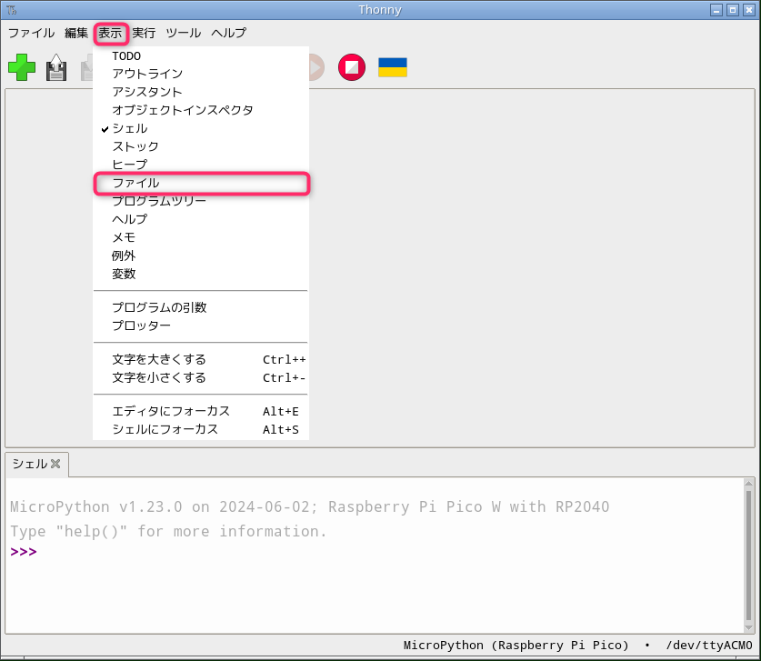
「Raspberry pi Pico」エリアのルート(/)フォルダ(ディレクトリ)を右クリックし、ダイアログを表示させます。
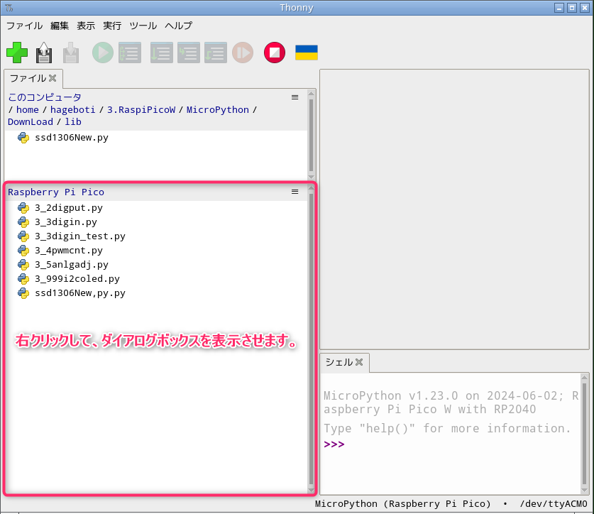
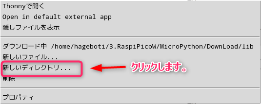
表示されたダイアログで「新しいディレクトリ…」をクリックします。
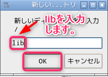
「新しいディレクトリ…」ダイアログの「新しいディレクトリ名を入力 /」に「lib」を入力し、「OK」をクリックします。
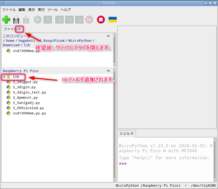
「lib」フォルダが追加されていることを確認後、「ファイルX」をクリックしてファイルを終了します。
lcd_api.pyモジュールの保存
Raspi4BのThonnyを起動し、次のコードをコピーして「エディタ」にペーストします。
ラズパイPicoWの「lib」フォルダ(ディレクトリ)に、ファイル名「 lcd_api.py」として保存します。
ファイル名は変えないでください。
# forked from https://github.com/T-622/RPI-PICO-I2C-LCD/
import time

class LcdApi:

    # Implements the API for talking with HD44780 compatible character LCDs.
    # This class only knows what commands to send to the LCD, and not how to get
    # them to the LCD.
    #
    # It is expected that a derived class will implement the hal_xxx functions.
    #
    # The following constant names were lifted from the avrlib lcd.h header file,
    # with bit numbers changed to bit masks.

    # HD44780 LCD controller command set
    LCD_CLR             = 0x01  # DB0: clear display
    LCD_HOME            = 0x02  # DB1: return to home position

    LCD_ENTRY_MODE      = 0x04  # DB2: set entry mode
    LCD_ENTRY_INC       = 0x02  # DB1: increment
    LCD_ENTRY_SHIFT     = 0x01  # DB0: shift

    LCD_ON_CTRL         = 0x08  # DB3: turn lcd/cursor on
    LCD_ON_DISPLAY      = 0x04  # DB2: turn display on
    LCD_ON_CURSOR       = 0x02  # DB1: turn cursor on
    LCD_ON_BLINK        = 0x01  # DB0: blinking cursor

    LCD_MOVE            = 0x10  # DB4: move cursor/display
    LCD_MOVE_DISP       = 0x08  # DB3: move display (0-> move cursor)
    LCD_MOVE_RIGHT      = 0x04  # DB2: move right (0-> left)

    LCD_FUNCTION        = 0x20  # DB5: function set
    LCD_FUNCTION_8BIT   = 0x10  # DB4: set 8BIT mode (0->4BIT mode)
    LCD_FUNCTION_2LINES = 0x08  # DB3: two lines (0->one line)
    LCD_FUNCTION_10DOTS = 0x04  # DB2: 5x10 font (0->5x7 font)
    LCD_FUNCTION_RESET  = 0x30  # See "Initializing by Instruction" section

    LCD_CGRAM           = 0x40  # DB6: set CG RAM address
    LCD_DDRAM           = 0x80  # DB7: set DD RAM address

    LCD_RS_CMD          = 0
    LCD_RS_DATA         = 1

    LCD_RW_WRITE        = 0
    LCD_RW_READ         = 1

    def __init__(self, num_lines, num_columns):
        self.num_lines = num_lines
        if self.num_lines > 4:
            self.num_lines = 4
        self.num_columns = num_columns
        if self.num_columns > 40:
            self.num_columns = 40
        self.cursor_x = 0
        self.cursor_y = 0
        self.implied_newline = False
        self.backlight = True
        self.display_off()
        self.backlight_on()
        self.clear()
        self.hal_write_command(self.LCD_ENTRY_MODE | self.LCD_ENTRY_INC)
        self.hide_cursor()
        self.display_on()

    def clear(self):
        # Clears the LCD display and moves the cursor to the top left corner
        self.hal_write_command(self.LCD_CLR)
        self.hal_write_command(self.LCD_HOME)
        self.cursor_x = 0
        self.cursor_y = 0

    def show_cursor(self):
        # Causes the cursor to be made visible
        self.hal_write_command(self.LCD_ON_CTRL | self.LCD_ON_DISPLAY |
                               self.LCD_ON_CURSOR)

    def hide_cursor(self):
        # Causes the cursor to be hidden
        self.hal_write_command(self.LCD_ON_CTRL | self.LCD_ON_DISPLAY)

    def blink_cursor_on(self):
        # Turns on the cursor, and makes it blink
        self.hal_write_command(self.LCD_ON_CTRL | self.LCD_ON_DISPLAY |
                               self.LCD_ON_CURSOR | self.LCD_ON_BLINK)

    def blink_cursor_off(self):
        # Turns on the cursor, and makes it no blink (i.e. be solid)
        self.hal_write_command(self.LCD_ON_CTRL | self.LCD_ON_DISPLAY |
                               self.LCD_ON_CURSOR)

    def display_on(self):
        # Turns on (i.e. unblanks) the LCD
        self.hal_write_command(self.LCD_ON_CTRL | self.LCD_ON_DISPLAY)

    def display_off(self):
        # Turns off (i.e. blanks) the LCD
        self.hal_write_command(self.LCD_ON_CTRL)

    def backlight_on(self):
        # Turns the backlight on.

        # This isn't really an LCD command, but some modules have backlight
        # controls, so this allows the hal to pass through the command.
        self.backlight = True
        self.hal_backlight_on()

    def backlight_off(self):
        # Turns the backlight off.

        # This isn't really an LCD command, but some modules have backlight
        # controls, so this allows the hal to pass through the command.
        self.backlight = False
        self.hal_backlight_off()

    def move_to(self, cursor_x, cursor_y):
        # Moves the cursor position to the indicated position. The cursor
        # position is zero based (i.e. cursor_x == 0 indicates first column).
        self.cursor_x = cursor_x
        self.cursor_y = cursor_y
        addr = cursor_x & 0x3f
        if cursor_y & 1:
            addr += 0x40    # Lines 1 & 3 add 0x40
        if cursor_y & 2:    # Lines 2 & 3 add number of columns
            addr += self.num_columns
        self.hal_write_command(self.LCD_DDRAM | addr)

    def putchar(self, char):
        # Writes the indicated character to the LCD at the current cursor
        # position, and advances the cursor by one position.
        if char == '\n':
            if self.implied_newline:
                # self.implied_newline means we advanced due to a wraparound,
                # so if we get a newline right after that we ignore it.
                pass
            else:
                self.cursor_x = self.num_columns
        else:
            self.hal_write_data(ord(char))
            self.cursor_x += 1
        if self.cursor_x >= self.num_columns:
            self.cursor_x = 0
            self.cursor_y += 1
            self.implied_newline = (char != '\n')
        if self.cursor_y >= self.num_lines:
            self.cursor_y = 0
        self.move_to(self.cursor_x, self.cursor_y)

    def putstr(self, string):
        # Write the indicated string to the LCD at the current cursor
        # position and advances the cursor position appropriately.
        for char in string:
            self.putchar(char)

    def custom_char(self, location, charmap):
        # Write a character to one of the 8 CGRAM locations, available
        # as chr(0) through chr(7).
        location &= 0x7
        self.hal_write_command(self.LCD_CGRAM | (location << 3))
        self.hal_sleep_us(40)
        for i in range(8):
            self.hal_write_data(charmap[i])
            self.hal_sleep_us(40)
        self.move_to(self.cursor_x, self.cursor_y)

    def hal_backlight_on(self):
        # Allows the hal layer to turn the backlight on.
        # If desired, a derived HAL class will implement this function.
        pass

    def hal_backlight_off(self):
        # Allows the hal layer to turn the backlight off.
        # If desired, a derived HAL class will implement this function.
        pass

    def hal_write_command(self, cmd):
        # Write a command to the LCD.
        # It is expected that a derived HAL class will implement this function.
        raise NotImplementedError

    def hal_write_data(self, data):
        # Write data to the LCD.
        # It is expected that a derived HAL class will implement this function.
        raise NotImplementedError

    def hal_sleep_us(self, usecs):
        # Sleep for some time (given in microseconds)
        time.sleep_us(usecs)
pico_i2c_lcd.pyモジュールの保存
Raspi4BのThonnyを起動し、次のコードをコピーして「エディタ」にペーストします。
ラズパイPicoWの「lib」フォルダ(ディレクトリ)に、ファイル名「pico_i2c_lcd.py」として保存します。
ファイル名は変えないでください。
# forked from https://github.com/T-622/RPI-PICO-I2C-LCD/
import utime
import gc

from lcd_api import LcdApi
from machine import I2C

# PCF8574 pin definitions
MASK_RS = 0x01       # P0
MASK_RW = 0x02       # P1
MASK_E  = 0x04       # P2

SHIFT_BACKLIGHT = 3  # P3
SHIFT_DATA      = 4  # P4-P7

class I2cLcd(LcdApi):

    #Implements a HD44780 character LCD connected via PCF8574 on I2C

    def __init__(self, i2c, i2c_addr, num_lines, num_columns):
        self.i2c = i2c
        self.i2c_addr = i2c_addr
        self.i2c.writeto(self.i2c_addr, bytes([0]))
        utime.sleep_ms(20)   # Allow LCD time to powerup
        # Send reset 3 times
        self.hal_write_init_nibble(self.LCD_FUNCTION_RESET)
        utime.sleep_ms(5)    # Need to delay at least 4.1 msec
        self.hal_write_init_nibble(self.LCD_FUNCTION_RESET)
        utime.sleep_ms(1)
        self.hal_write_init_nibble(self.LCD_FUNCTION_RESET)
        utime.sleep_ms(1)
        # Put LCD into 4-bit mode
        self.hal_write_init_nibble(self.LCD_FUNCTION)
        utime.sleep_ms(1)
        LcdApi.__init__(self, num_lines, num_columns)
        cmd = self.LCD_FUNCTION
        if num_lines > 1:
            cmd |= self.LCD_FUNCTION_2LINES
        self.hal_write_command(cmd)
        gc.collect()

    def hal_write_init_nibble(self, nibble):
        # Writes an initialization nibble to the LCD.
        # This particular function is only used during initialization.
        byte = ((nibble >> 4) & 0x0f) << SHIFT_DATA
        self.i2c.writeto(self.i2c_addr, bytes([byte | MASK_E]))
        self.i2c.writeto(self.i2c_addr, bytes([byte]))
        gc.collect()

    def hal_backlight_on(self):
        # Allows the hal layer to turn the backlight on
        self.i2c.writeto(self.i2c_addr, bytes([1 << SHIFT_BACKLIGHT]))
        gc.collect()

    def hal_backlight_off(self):
        #Allows the hal layer to turn the backlight off
        self.i2c.writeto(self.i2c_addr, bytes([0]))
        gc.collect()

    def hal_write_command(self, cmd):
        # Write a command to the LCD. Data is latched on the falling edge of E.
        byte = ((self.backlight << SHIFT_BACKLIGHT) |
                (((cmd >> 4) & 0x0f) << SHIFT_DATA))
        self.i2c.writeto(self.i2c_addr, bytes([byte | MASK_E]))
        self.i2c.writeto(self.i2c_addr, bytes([byte]))
        byte = ((self.backlight << SHIFT_BACKLIGHT) |
                ((cmd & 0x0f) << SHIFT_DATA))
        self.i2c.writeto(self.i2c_addr, bytes([byte | MASK_E]))
        self.i2c.writeto(self.i2c_addr, bytes([byte]))
        if cmd <= 3:
            # The home and clear commands require a worst case delay of 4.1 msec
            utime.sleep_ms(5)
        gc.collect()

    def hal_write_data(self, data):
        # Write data to the LCD. Data is latched on the falling edge of E.
        byte = (MASK_RS |
                (self.backlight << SHIFT_BACKLIGHT) |
                (((data >> 4) & 0x0f) << SHIFT_DATA))
        self.i2c.writeto(self.i2c_addr, bytes([byte | MASK_E]))
        self.i2c.writeto(self.i2c_addr, bytes([byte]))
        byte = (MASK_RS |
                (self.backlight << SHIFT_BACKLIGHT) |
                ((data & 0x0f) << SHIFT_DATA))
        self.i2c.writeto(self.i2c_addr, bytes([byte | MASK_E]))
        self.i2c.writeto(self.i2c_addr, bytes([byte]))
        gc.collect()
LCDの I2Cアドレスを確認
Raspi4BのThonnyを起動し、次のコードを「エディタ」に入力するか、リストをコピーしてペーストします。
#モジュールの読み込み(インポート)
from machine import Pin, I2C

#I2Cを利用するため、オブジェクト(i2c)を作成
i2c = I2C(0,sda=Pin(16), scl=Pin(17), freq=400000)

#I2Cのアドレス確認(16進数)
for addr in i2c.scan():
    print("I2C 16進法アドレス: ", hex(addr))
Thonnyの「F5」キーを押して、プログラムを実行します。
「I2C 16進法アドレス: 0x27」がThonnyのシェルに表示されます。
LCDの I2Cアドレスは「0x27」であることが確認できます。
確認後、Thonnyの「Ctrl + F2」キーを押して、停止します。
文字表示プログラム
画面上のどこに文字を表示させたいかを選択し、液晶ディスプレイにメッセージを送ると、文字が表示されます。
文字を表示したい場所を指定しなければ、最初に空いているスペースに、文字が表示されます。
文字表示プログラムは「Hello, World!」を1行目に3秒間表示した後、表示を消去します。
続いて「Welcome To」を1行目に表示して、3秒間経過後、2行目に「ラズパイ Pico W」を表示します。
Raspi4BのThonnyを起動し、次のコードを「エディタ」に入力するか、リストをコピーしてペーストします。
| ***ご購入前に、必ずお読みください。*** プログラム等は「The MIT License」または「The 3-Clause BSD License」のライセンスに則り、無保証で販売しておりますので、不具合に関するお問い合わせ及び返金については、受け付けておりませんのでご了承ください。 |

